3D Scanning Systems and Usage Areas
With the help of developing technology, products have more shaped lines than 10 years ago.
is being designed. Especially in the automotive industry, from external appearance to interior parts and details
All parts have formed appearances defined as surface modeling in the CAD environment.
is happening. Today, with the developments in optical measurement technology, these forms can be easily
can be measured. This need for 3D scanning systems, which arose from the need for production from clay models in the automotive industry, has begun to be used frequently in the fields of retrospective engineering and quality control.

3D scanning systems are divided into two main groups: touch and non-touch systems.
They are touch or probe systems, mechanical arm systems and CMM. A few
Thanks to a measuring probe attached to the end of the axis mechanical arm, the coordinates are adjusted to the desired point.
The coordinates of the point are measured precisely with the touched probe. Surface information with these systems
The coordinates of a certain number of points can be obtained.
Obtaining free-form surface information with non-touch optical systems is important for both product development and
engineering offices specialized in reverse engineering and quality control processes, as well as
design and product development, quality control, molding rooms, etc. of large industrial organizations. like
It is important for the departments. With these systems, the entire surface form can be created with very high precision.
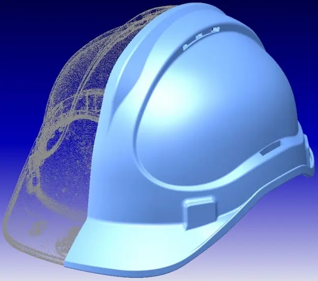
is obtained and CAD model creation, rapid prototyping and CNC processing are carried out.
is getting ready.
Although there are various types of 3D scanning systems and non-touch systems and each has different usage areas,
laser line systems and structured light pattern (grid projection, fringe) systems or
Topogrammetric systems are more commonly used than others.
Laser line systems, among the non-touch optical scanning systems, create a laser cross-section on the object.
They work on the principle of dropping the object and moving this section on the object. Measurement
method, the laser section is deformed on the object and this deformation information is recorded on CCD.
It is taken by digital camera. Portable hand-held models as well as mechanical
There are also some that are attached to the arm end. Additionally, measurement can be automated by connecting it to the robot arm.
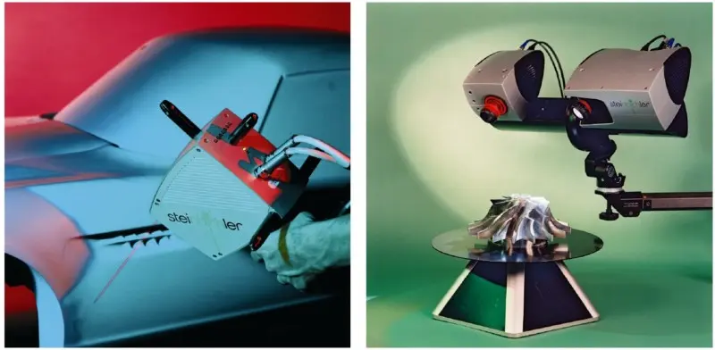
can be brought. An example of these systems is Steinbichler T-SCAN. A portable system
Because of this, the products to be digitized can be scanned in their own environment. Thus
Time-consuming pre-scanning preparations are eliminated. Even inexperienced people
With this system that can be used, scanning by moving as if painting with a paintbrush
It is performed and can be viewed in real time on the monitor during scanning. 90mm
It allows scanning of large objects with its scanning width.
3D scanning systems Usage Areas
- The manufacturer has not produced a part for a long time and wants to produce it again,
- The original design has insufficient documentation,
- The original manufacturer of a product no longer exists, but customers need this product,
- The original documentation of the product is lost or does not exist at all,
- Some bad features of the product need to be redesigned,
- Measuring the good features of the product based on long-term use of the product,
- Analyzing the good and bad features of the competitor product,
- Discovering new ways to improve the performance and features of the product,
- Obtaining competitive benchmarking methods to understand competing products and develop better products,
- The original CAD model is not sufficient for changes or current production methods,
- The original manufacturer company demands excessive fees to supply parts,
- Updating outdated parts or old production processes with current and cheaper technologies
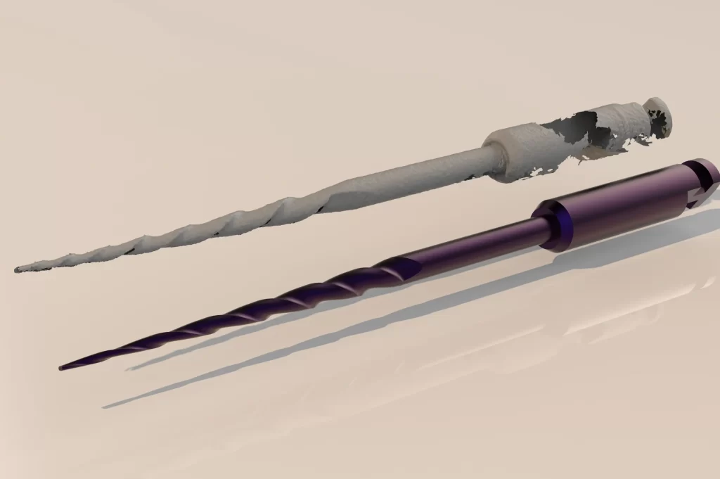
Retroactive engineering provides solutions to such requests and problems. Digitization systems are used as a technological convenience in solving these processes. The part is digitized through these systems and can be made ready for CAD model creation.
These periods vary depending on different systems. The time given here is Breuckman optoTOP HE 3D
It is the catalog value of the digitization system.
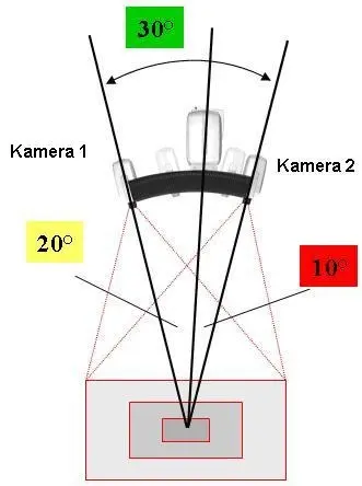
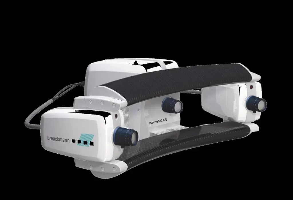
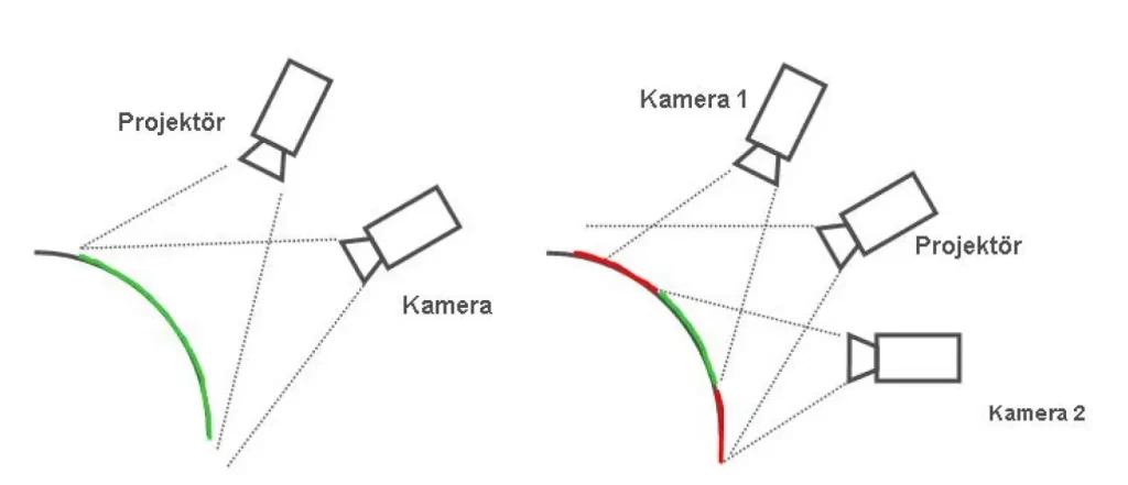
Single camera system Figure 4. Dual camera system, Asymmetrically placed dual camera system (Breuckmann STEREOSCAN)
