Reverse Engineering – 3d Scanning 3d scanning
Defne Engineering has started to provide services to its customers faster, with higher quality and at lower costs, with the new software it has started to use in optical scanning and Reverse Engineering (Reverse Engineering). With the help of CATIA V5 software, which it acquired as a new investment, it started to carry out reverse engineering projects in the CATIA environment.
Reverse Engineering Study in CATIA; Helmet Modeling and Modification:
The work carried out together with the manufacturer on new models upon the request of the manufacturer regarding occupational safety is briefly summarized below. The company has prepared a model for the new type of helmet it wants to develop. A new form was created by covering the hand-prepared model with plaster and model material on a standard helmet. The created form was considered together with another type of helmet model currently produced by the manufacturer, and the project was started to create a new design by combining the popular parts of these two different types of helmet. In this project, which started by considering two different helmet types, the stage (spur) above the second model will be added to the first model in line with customer requests, based on the first model, and production will begin with the new model. However, since the model will be produced by the plastic injection method, the computerized design of the new product will be completed in the CATIA program, taking into account the mold design required for the production of the part.
Preparatory Procedures:
There are a number of preparation processes that must be applied first in solid-surface modeling works from measurement data (STL). By performing these operations, problems that may be encountered during the modeling phase are minimized.
First of all, the STL data obtained as a result of optical scanning should be cleaned from unwanted mesh parts that do not belong to the model, and the separated mesh parts remaining in the air should be deleted. Then, the mesh parts that are topologically incorrect (non-manifold, crossing face, redundant face) should be corrected. The holes in the data should be closed, if necessary, the data should be smoothed and decimated within tolerances and placed on an axis set suitable for modeling.
CAD Modeling in CATIA
After the preparation processes mentioned above, the STL data is ready for modeling with the help of the Reverse Engineering module in CATIA.
Unlike modeling from scratch, modeling from STL data is a more difficult process in terms of both time and effort. Tolerances and changes determined by the customer make this process even more challenging. In addition, situations that require high surface quality, as in this project, require more patience, attention, experience and knowledge.
In modeling studies from STL, the following modules of CATIA are mainly used in terms of the operation of the process:
- Digitized Shape Editor
- Quick Surface Reconstruction
- Generative Shape Design
- Part Design
STL data imported with Digitized Shape Editor can be subjected to the above-mentioned preparation processes with various tools in this module, and can also be made ready for modeling with the help of external software. In this project, external software was used to carry out the preparation processes.
In the Quick Surface Reconstruction module, curves such as Section Curve, Feature Curve, 3D Curve and main Primitive or Freeform surfaces are directly obtained via STL. These curves and surfaces can be used directly in modelling, or they can also serve as a reference for new curves and surfaces to be created. The tools in this module are also used to determine trim lines and boundaries. In this project, the curves and surfaces taken from this module were used as references to determine the form of the model, trim lines and various boundaries.
In Generative Shape Design modules, new and higher quality surfaces are created from reference curves and surfaces taken from QSR.
This is the most time-consuming and challenging part of modeling projects from STL. The biggest factor that makes this process difficult is that these created surfaces fit within the tolerances of the STL measurement data (low measurement deviation) and that the surface and surface transitions are very good. Getting an accurate and acceptable result is possible with trial and error. Therefore, it may be necessary to try different surface commands many times by entering different parameter values.
When the desired results are obtained, the surface modeling is tried to be finalized through the necessary surface operations (such as split, trim, join, etc.).
The created surface model is made solid in the Part Design module. After this stage, other features of the physical model (Dress-up features) are added and the model is brought to its final form.
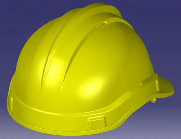
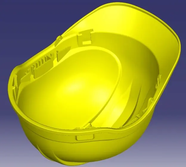
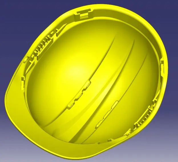
In the first stage of this project, the modeling of the first type of helmet was done using the modeling method outlined above, in addition, the stage above the second type of helmet was added to the model in line with customer requests.
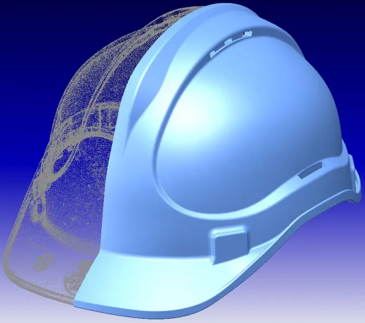
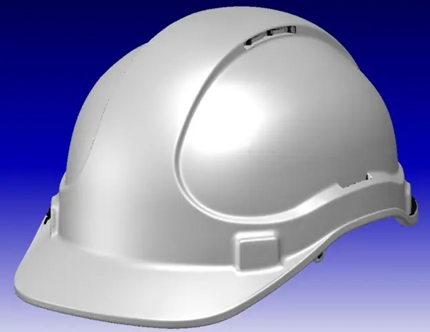
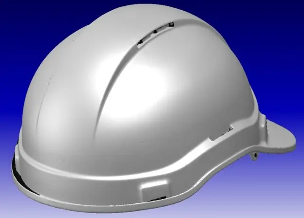
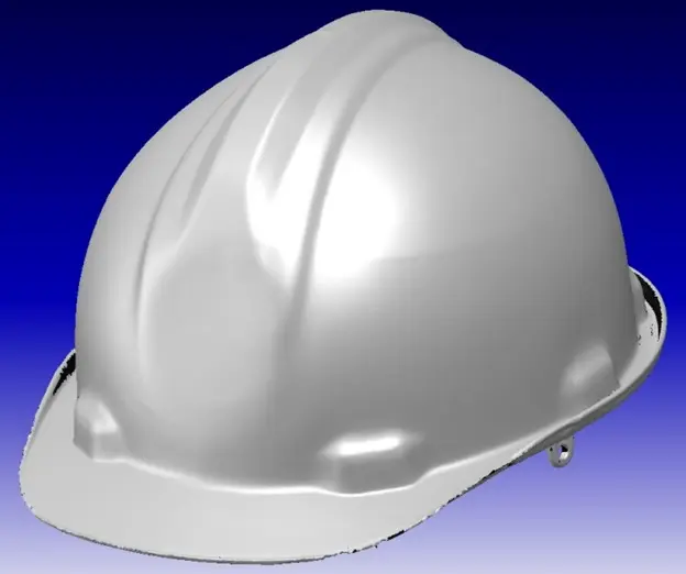
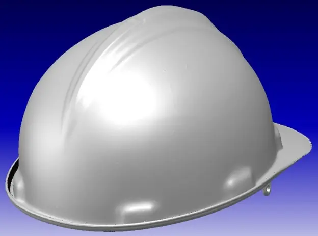
Completion times for STL modeling projects, which are longer and more laborious than other modeling processes, are generally in days. This project took approximately 2 days to complete. The finished version of the model can be seen in the pictures below.
Quality control
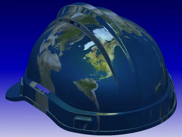
Highlight and Environment Mapping Analysis tools were used to see the quality of the surface of the created CAD model. The results are seen in the pictures below.
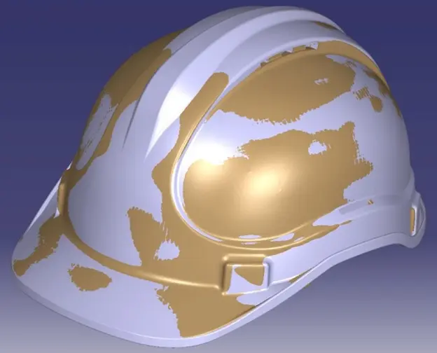
Highlight Analysis compares the angle between the surface normals and a direction specified by the user. With this method, the continuity in surface transitions and connections is checked.
Highlight analysis
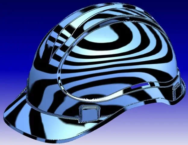
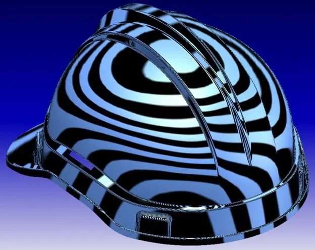
In surface analysis with the environmental mapping technique, a picture is placed on the model and deformations in this picture are observed. The lack of deformations and the smooth appearance of the picture indicate the surface quality. Preferring curvature continuity while modeling will provide better results from this analysis as it will give smoother surface transitions.
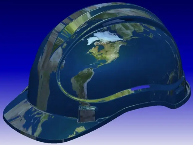
The control procedures listed above were used not only at the end of the modelling, but also during the modeling process, and these tools were used to check whether the created surfaces reached an acceptable level.
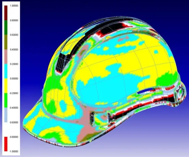
After all the modeling studies, as a final stage, the measurement control of the CAD data resulting from the reverse engineering work carried out in CATIA with STL data is carried out. In this way, it can be seen dimensionally how much the model deviates from the STL data.
In backward engineering or reverse engineering studies, CAD modeling studies were carried out based on the point clouds formed as a result of 3D measurement and optical scanning. In CAD modeling, the main principles, modeling stages and control method of the RE2 package, the reverse engineering module of the CATIA program, are briefly explained.
This article was published in March 2008 and you can find the publication link below.
You can review it from the published link.
This study, which is one of the first published examples of reverse engineering projects, has become a reference for many people carrying out localization studies.